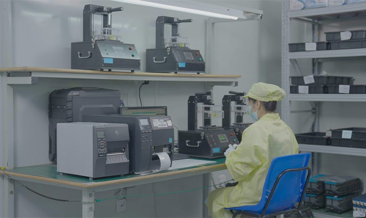
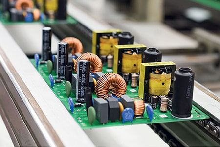
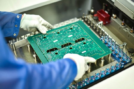
The common testing methods for PCBA circuit boards mainly include the following
Manual Testing: This is a testing method that relies directly on vision to confirm the placement of components on the PCB through visual comparison. However, due to the large number and small size of components, this method is becoming increasingly inapplicable. Additionally, some functional defects may not be easily detectable, and data collection can be challenging.

Automated Optical Inspection (AOI): Also known as automated visual testing, it is performed by a dedicated inspection instrument. This method is commonly used before and after reflow and is effective for checking the polarity of components. It is easy to follow-up on diagnostics, but it may not be as effective at identifying shorts.
Flying Probe Tester: Due to improvements in mechanical accuracy, speed, and reliability, flying probe testing has become popular in recent years. It is particularly suitable for prototype manufacturing and low-volume manufacturing, where fast conversion and fixture-free testing systems are required.
Functional Testing: This is a testing method specific to certain PCBs or units, completed using dedicated equipment. Functional testing mainly includes final product testing (Final Product Test) and the latest physical model (Hot Mock-up).
Manufacturing Defect Analyzer (MDA): The main advantage of this testing method is its low upfront cost, high output, ease of diagnostics, and fast and complete short circuit and open circuit testing. However, it cannot perform functional testing, usually lacks test coverage indication, requires fixtures, and has high testing costs.
In addition, there are some specific testing methods, such as:
Voltage Withstand Test: Detects the voltage withstand capability of the circuit board, requiring a voltage withstand tester.
Leakage Current Test: Checks if the leakage current of the circuit board is within the required range, requiring a leakage current tester.
Salt Spray Test: Checks the corrosion resistance of the circuit board, requiring a salt spray test chamber.
Impedance Test: Checks if the circuit board's wiring can operate normally, requiring an ohmmeter.
Vibration Test: Detects if the circuit board can pass different levels of random vibration testing, requiring a vibration tester.
High Temperature and High Humidity Test: Checks the applicability of the circuit board under severe conditions of high temperature and high humidity, requiring a constant temperature and humidity test chamber.
Solder Strength Push Test: Tests if the soldering strength of components meets the requirements, requiring a push tester.
The selection and application of these testing methods depend on specific testing requirements and conditions. In practical operations, it may be necessary to combine multiple testing methods to conduct comprehensive and accurate testing based on the characteristics and design requirements of the circuit board.


