poe@pcbamake.com


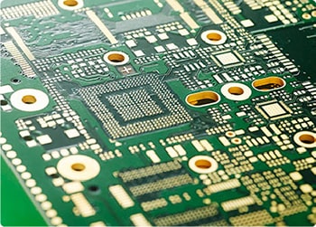
How is PCB Conductive Via Plugging Done?
Conductive vias (vias) are used to achieve electrical interconnection in multiple layers of circuits. As electronic products become lighter, thinner, shorter, and smaller, PCB density and assembly complexity have increased significantly. With the widespread use of surface-mounted metal (SMT) and base-gauge grid arrays (BGAs), via plugging has become a critical process for assembly yield and reliability. We replace traditional aluminum sheet via plugging with white screen printing, achieving simultaneous solder mask and via plugging, ensuring stable production and high yield.
Application Requirements for Via Plugging
Depending on assembly and reliability goals, customers typically have three types of via plugging requirements:
Conduction Only: Copper is sufficient within the via; solder mask plugging is optional.
Solderable Fill: The via must contain a certain thickness (approximately 4 μm) of tin-lead (or lead-free alloy). Solder mask ink must not enter the via to prevent tin beads from forming.
Solder mask plugging: The holes must be completely filled with solder mask ink, making them opaque. The surface must be smooth and free of tin rings and beads.
Why are via plugging performed?
Preventing short circuits: Preventing solder from flowing through the holes to the component surface during wave soldering, thus preventing bridging. When opening holes in BGA pads, plugging is required before surface treatment (such as gold plating) to ensure BGA soldering.
Preventing residue: Preventing flux residue from remaining in the holes, reducing the risk of corrosion and ionic contamination.
Facilitating testing: PCBA in-circuit testing/functional testing often requires vacuuming to create negative pressure. Plug-in vias facilitate sealing and fixture stability.
Preventing cold solder joints: Preventing surface solder paste from flowing into the holes, resulting in insufficient soldering.
Preventing solder beads: Reducing the risk of solder beads ejecting and short circuits during wave soldering or reflow.

Assembly Board Via Flatness Requirements
For BGA/fine-pitch IC areas, the surface after via plugging must be flat, with bumps ≤ ±1 mil. The hole edge must not be reddened by tinning, and no tin beads should be trapped inside the hole to avoid rework and hidden defects.
Common Via Plug Solutions and Process Flows
Option A: Solder Mask Ink Via Plug (White Screen Via Plug, commonly used for through-hole and blind vias that do not carry high current).
Typical Process: Drilling → Desmear/Drill Desmear → Electroless Copper Plating → Copper Electroplating (Barrel Forming) → Dry Film/Etch Imaging → Solder Mask Pretreatment → White Screen Via Plug (Ink Screen Printing/Vacuum Assisted) → Pre-bake → Full-Board Solder Mask Exposure → Development → Curing → Surface Treatment (HASL/ENIG/OSP, etc.).
Advantages: Moderate cost, can be produced simultaneously with solder mask, can achieve excellent surface flatness, and is SMT-friendly.
Risks and Controls: Ink viscosity and screen parameters must be controlled to avoid bubbles and pinholes; pre-bake and cure curves must be aligned to avoid "oil popping" and "oil shedding."
Option B: Conductive Silver Paste Via Plug (Conductive Fill + Copper Cap Plating, Suitable for VIPPO and Thermal/Electrical Performance Enhancement)
Process: Drilling/Plated Copper/Through-Hole Plating → Vacuum/Screen-Printed Conductive Silver Paste Filling → Thermal Curing → Surface Grinding/Smoothing → Thickened Copper Cap Plating (Cap Plating) → Solder Mask → Surface TreatmentRisks and Controls: Voids must be prevented; Cure shrinkage and CTE must be well matched; Cleanliness and ion residue requirements are high.
Option C: Copper Electroplating Via Filling (Pulse/PR Copper Filling, Suitable for Micro Blind Vias, Stacked Micro Blind Vias, and VIPPO)
Process: Laser Drilling Micro Blind Via → Desmearing/Plasma Desmearing → Plated Copper → Pulse/Reverse Pulse Electroplating Copper Filling (Bottom-Up) → Overplating/Smoothing → Cap Plating → Solder Mask → Surface TreatmentLimitations: Does not improve thermal conductivity and is not suitable for high current/heat paths.
Quality Control Points
Cross-section Assessment: 100% fill, no voids, no ink sag; copper thickness at the via knee meets IPC Class 2/3 standards.
Flatness and Coplanarity: Target ≤15 μm in the BGA area to avoid solder paste evacuation.
Electrical/Thermal Performance: Measure DC resistance and thermal resistance for conductive fill items; perform thermal cycling and IST reliability testing on high-power boards. Cleanliness: Ionic contamination, in-hole residue, and cure completeness to prevent CAF and outgassing.
Soldermask adhesion: No oil loss or cracking after hot air leveling (HASL) or reflow.
Design and Document Marking Recommendations
Clearly mark: Via type (through hole/micro blind hole/stacked hole), whether VIPPO, and via plugging material (soldermask plug hole/conductive silver paste/copper fill hole).
Dimensions and Stackup: Provide the hole diameter, board thickness, interlayer dielectric thickness, and target impedance to facilitate manufacturability and cost assessment.
Package Area Strategy: Prioritize VIPPO or copper-filled micro blind hole for BGA areas; prioritize conductive fill or copper fill for power and heat dissipation areas.
Mask and Pad: Define soldermask coverage, mask dam width, and plating dam location.
Wave Solder Products: Mark surfaces requiring plugging and selective coating of vias to prevent tin penetration and solder beading.
About Hot Air Leveling (HASL) and Via Plugs: HASL uses hot air to remove excess solder while preserving the pad plating. Inadequate via plugging or unsealed openings can easily lead to tin beads and ink blistering during HASL or reflow. Recommendations:
Use vacuum via plugging or secondary reprinting to ensure light-tightness and full vias;Appropriately install ground via "test coupons" on HASL boards to spot-check for cracking and oil loss.
What We Can Do:
PCB Manufacturing: White solder mask via plugging, conductive silver paste via plugging, copper electroplating via filling, VIPPO, stacked micro-blinds; impedance control and high-TG materials; strict dielectric/copper thickness tolerances.Functional and Reliability Testing: Cross-sectional inspections, resistance/thermal imaging, near-field, and reflow stress assessments.
Global Shipping: From pilot runs to mass production, with full traceability and international logistics.
If you need to implement via-in-pad in BGA areas, improve heat dissipation and current carrying in power paths, or prevent solder penetration during wave soldering, we can provide material selection, stackup recommendations, and cost/yield trade-offs. Contact PCBAMake for a manufacturability review and sample proposal.
If you have PCB/PCBA/OEM/ODM needs, please contact us, We will reply within 2 hours, and complete the quotation within 4 hours or less upon request.
Delivery Services

Verified by

Link Us on