Orders@pcbamake.com

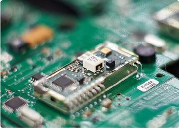
The answer lies in the layered design of multilayer PCBs. From routers costing hundreds of dollars to servers costing tens of thousands of dollars, from Bluetooth headsets to automotive electronic control systems, multilayer PCBs use "three-dimensional wiring" to break through spatial limitations and simplify complex circuits.

Multilayer PCB
Definition: A rigid or rigid-flex circuit board constructed by laminating two or more layers of conductive copper foil with a dielectric (insulating layer) and laminating, interconnected by vias.
Typical range: 4–40 layers (4/6/8/10/12 layers are common). More layers provide greater routing freedom, power supply, and shielding capabilities, but also increase cost and manufacturing difficulty.
Key elements: Signal layer, ground plane, power plane, inner layer signal layer, dielectric (prepreg/core), and vias (through hole, blind/buried via, micro blind via).
Why Choose a Multilayer PCB?
High-Density Routing: Addresses BGA/high-pin-density devices, alleviating routing congestion and via stacking.Typical Applications: Smartphones/tablets, routers and switches, automotive ECUs, industrial control, medical equipment, servers and storage, AR/VR, IoT modules, etc.
Functions of Each Layer in a Multilayer PCB
Signal LayerKey Points: Avoid overlaying pads; fonts and line widths must meet factory minimum readability specifications.
Key Design Points for Multilayer PCBs
Impedance and Signal Integrity (SI)Length matching: Follow protocol specifications (e.g., DDR and PCIe requirements). Trace bends should preferably be 45° or circular.
Return Current Paths and EMC
Maintain a continuous reference plane; use stitching vias to bridge return currents at crossovers.High-frequency/fast-edge signals should not be split across ground planes. If crossovers are necessary, add dense stitching vias nearby. Sensitive analog areas should be partitioned from strong interference sources (motor drive, DC-DC) and isolated with ground planes.
Power Integrity (PI) and Decoupling
The power plane and ground plane should be close together, and the dielectric should be as thin as possible to maximize plane capacitance.Wide high-current paths, add copper, and use multiple vias; use copper strips/heat sinks as needed.
Vias and Interconnects
Through vias: Versatile and low-cost; be aware of the impact of via stubs on high-speed connections.Backdrilling: Remove via stubs from high-speed networks to reduce reflections and resonance. Recommendations: Minimize vias for high-speed networks; add pairs of stitching vias at reference plane transitions.
Thermal Design
Incorporate a large copper surface and thermal via arrays (via-in-pad/near-near vias) on the bottom of power devices.Thermal relief pads (thermal relief) balance solderability and heat dissipation.
Manufacturability (DFM/DFA)
Avoid extremely thin isolated copper and sharp corners; maintain a manufacturable solder bridge width.Panelization: Define the processing edge, process holes, fiducials, and panel separation method (V-cut/stamp hole) in advance.

Multilayer PCB Material and Process Selection
Base Material: FR-4 (most applications), High-Tg FR-4 (high temperature), High-speed/High-frequency materials (low Dk/Df, such as mixed-press Rogers + FR-4).Via Aspect Ratio: Typical for through-holes: ≤8–10:1; higher requirements require reliability assessment.
Multilayer PCB Quality and Testing
Standards and Grades: IPC-6012 Class 2 (General Purpose), Class 3 (High Reliability/Automotive); UL-certified materials and flame retardant grades (e.g., UL94 V-0) available.Reliability: Thermal cycling, damp heat, CAF evaluation (for high-voltage and fine-pitch applications), and micro Blind Via stacking/staggering verification (refer to IPC-2226).
For multilayer board stackup recommendations, controlled impedance calculations, and a sample quote for your project, please contact PCBAMake's technical and sales team. We support prototypes from 2–40 layers to low-volume production, and provide design for manufacturability (DFM) reviews and production ramp-up support.
If you have PCB/PCBA/OEM/ODM needs, please contact us, We will reply within 2 hours, and complete the quotation within 4 hours or less upon request.
Delivery Services

Verified by

Link Us on