poe@pcbamake.com


In today’s electronics industry, PCB quality directly determines the performance and reliability of the end product. From consumer devices to automotive and industrial systems, consistent inspection throughout the production process is critical. This article provides a clear overview of the main PCB inspection methods and the equipment commonly used to ensure stable, high-precision results.
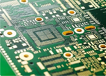
1. Visual Inspection
Visual inspection is the first stage of quality control and helps catch surface issues before moving into more advanced testing.
Common checks include:
Scratches, dents, contamination
Solder mask uniformity
Pad alignment and surface finish quality
Missing or damaged features
Typical tools:
Magnifying lamps
Industrial microscopes
HD inspection cameras
Visual inspection is ideal for quick screening and preventing early-stage process defects.

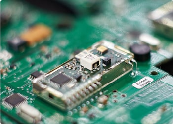
2. AOI (Automated Optical Inspection)
AOI systems use high-resolution cameras and image-processing algorithms to detect defects automatically. They are widely used for both bare PCB fabrication and PCBA inspection.
AOI can identify:
Track width violations
Shorts, opens, and spacing errors
Missing, misaligned, or reversed components (for PCBA)
Insufficient solder or solder bridges
Why it’s essential:
High speed, consistent accuracy, and fully automated detection make AOI suitable for both prototypes and mass production.
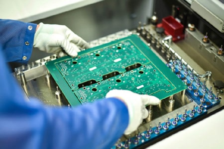
3. Electrical Test (E-Test)
Electrical testing ensures that the PCB’s circuitry matches the design intent. It is one of the most critical steps for final verification.
Detects issues such as:
Open circuits
Short circuits
Incorrect or missing connections
Equipment options:
Flying-probe testers (ideal for prototypes and small batches)
Bed-of-nails fixtures (for mass production at high throughput)
Electrical testing provides direct confirmation of PCB functionality before assembly.
4. X-Ray Inspection
X-ray inspection is essential for examining internal structures and hidden solder joints that cannot be verified visually.
Typical applications:
BGA and QFN solder joints
Voids and internal cracks
Multilayer alignment and via integrity
Copper distribution inside plated through-holes
Equipment used:
2D or 3D X-ray inspection systems
X-ray inspection is especially important for high-density, multilayer, and advanced packaging designs.
5. Cleanliness Testing & Ionic Contamination
Surface cleanliness directly affects long-term reliability, especially for high-frequency, automotive, medical, and aerospace electronics.
What it evaluates:
Residual flux
Ionic contamination
Surface insulation resistance (SIR)
Common equipment:
Ion chromatography systems
ROSE (Resistivity of Solvent Extract) testers
SIR test chambers
Maintaining clean surfaces reduces the risk of corrosion, leakage current, and premature failure.
6. Micro-Section (Cross-Section) Analysis
Micro-sectioning provides a detailed cross-section view of the PCB’s internal structure.
Used to inspect:
Copper plating thickness
Via quality and barrel integrity
Layer alignment
Solder joint micro-structure
Lamination quality
Equipment:
Micro-section preparation equipment
Metallographic microscopes
This method is essential for failure analysis, material evaluation, and validating complex PCB stack-ups.
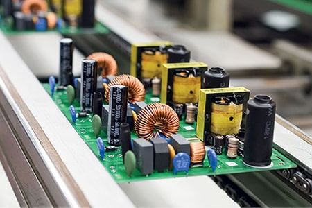
A robust PCB inspection process is a combination of several complementary methods. By integrating visual checks, AOI, electrical testing, X-ray analysis, and micro-section evaluation, manufacturers can ensure consistent quality and reliable performance for every order.
At PCBAMake, we follow strict inspection standards throughout PCB manufacturing and assembly. Our team provides:
Full inspection reports
Electrical testing
AOI and X-ray services
Whether you need prototypes or mass production, we ensure every board meets global quality and performance expectations.
If you have PCB/PCBA/OEM/ODM needs, please contact us, We will reply within 2 hours, and complete the quotation within 4 hours or less upon request.
Delivery Services

Verified by

Link Us on